
How to repair P6 outdoor LED display sign board screen?
- 11. Introduction
- 22. Common symptoms of P6 outdoor LED failures
- 33. LED display repair: essential tools checklist
- 44. Step-by-step guide to repairing a P6 outdoor LED module
- 4.1Step 1 - Setting up the repair environment
- 4.2Step 2 - Safely remove the damaged LEDs
- 4.2.11. Module preparation & safe disconnection
- 4.2.22. Removing the mask & waterproof glue
- 4.2.33. Desoldering the faulty LED lamp via hot air gun
- 4.3Step 3 - Installation & soldering of the new LED
- 4.3.11. PCB copper pads cleaning & flux preparation
- 4.3.22. Strict LED polarity alignment
- 4.3.33. Soldering the new LED pixel
- 4.4Step 5: Post-Repair Inspection & Module Re-Assembly
1. Introduction
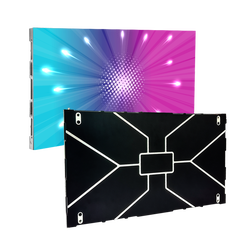
Outdoor LED displays are high-value advertising assets, but long-term exposure to harsh weather conditions can lead to unexpected technical issues. Among various pitches, the P6 outdoor LED display screen is one of the most widely used models for commercial sign boards. If your P6 screen is experiencing glitching, dead pixels, or partial blackouts, this professional troubleshooting guide from the CHIFE factory will help you locate and fix the problems step by step.

2. Common symptoms of P6 outdoor LED failures
Before grabbing your tools, you must accurately diagnose the issue. Here are the most common P6 outdoor screen failures:
Single module blackout or flickering: Usually caused by a loose ribbon signal cable or a loose 5V DC power cable behind the specific P6 module.
Large area blackout (multiple cabinets): Typically indicates that a receiving card has lost power, the main signal CAT6 cable is disconnected, or a meanwell power supply has failed.
Dead pixels or constant bright spots: Caused by a short circuit or cold welding of individual SMD3535 LED lamps due to rain penetration or silicone aging.
3. LED display repair: essential tools checklist
Before you begin repairing your LED display module, you need to gather the right equipment. Having the necessary LED repair tools ensures the maintenance process is efficient and successful.
Here is a checklist of the tools you need to prepare:
Soldering Tools:Soldering Iron/Air Gun (Heat Gun)/Tin (Solder)/Copper Wire (Desoldering Braid/Wick)
Testing & Diagnostics:Multimeter/Receiving Card (for testing/configuration)/Power Supply/
Hand Tools:Tweezers/Screwdriver (Standard)/Mask Screwdriver (Specific tool for LED mask removal)
Cables & Accessories:Ribbon Cable/Power Cable/Black Glue (Sealant/Adhesive)
Components for Replacement:Module with Dead LEDs (The damaged module)/New LEDs (Replacement diodes)/New Module (If module replacement is needed)

4. Step-by-step guide to repairing a P6 outdoor LED module
Step 1 - Setting up the repair environment
First, let's connect the LED modules and power up all the tools.I'll switch on the air gun and soldering iron. Once everything's powered up, let's confirm all these new friends are ready for action! (Wish me luck as I start this repair journey.)
Next, I'll connect the power supply to our source—here it's 220V. A quick note: Power supplies vary globally (110V ~ 240V). Always double-check you’re using the correct voltage for your country.
Now, it’s time to breathe life into the screen. I'll power the receiving card and the LED module, and command the screen to display a series of pure colors: White, Red, Green, and Blue.
Ah! I see you, little faulty LED! Gotcha. Time to take you to the repair "hospital" for some urgent care.
Step 2 - Safely remove the damaged LEDs
1. Module preparation & safe disconnection
Before you begin to repair dead pixels on the LED screen, you must guarantee the electronic components are completely de-energized.
Disconnect the power cable first: Cut off the 5V DC power supply to avoid short circuits.
Unplug the ribbon data cable second: Safely remove the signal ribbon cable.
⚠️ CRITICAL WARNING: Always follow this specific sequence! Disconnecting the data cable while power is still active can permanently fry the driving IC.
2. Removing the mask & waterproof glue
To access the damaged SMD3535 LED lamp, you need to clear the protective layer without harming neighboring components:
Remove the LED mask: Carefully detach the small plastic mask (jacket) covering the faulty LED area. Only remove the specific section directly above the damaged pixel.
Peel away the waterproof adhesive (for outdoor LED modules): Since an outdoor LED display sign board requires high weather resistance, the diode will be sealed with potting glue. Use precision tweezers to carefully peel away the black waterproof adhesive covering the target pixel.
3. Desoldering the faulty LED lamp via hot air gun
Desoldering requires precise temperature control to protect the multi-layer LED PCB board:
Adjust equipment settings: Set both your hot air gun’s temperature and wind speed to Level 2 (or approximately 320°C depending on your station). Excessive heat will cause the PCB pads to delaminate.
Maintain a 90-degree angle: Hold the hot air gun completely upright at a 90-degree vertical angle directly over the faulty diode. This prevents lateral heat dissipation from accidentally damaging healthy neighboring pixels.
Gently remove the LED: Watch closely as the original solder on the PCB melts into a liquid state. Once the solder liquefies, the dead LED will become loose. Gently nudge and lift the faulty LED out with your tweezers.
❌ IMPORTANT NOTE: Never use brute force! Tugging a cold LED will instantly tear the delicate copper soldering pads off the PCB board, rendering the entire P6 module beyond repair.

Step 3 - Installation & soldering of the new LED
1. PCB copper pads cleaning & flux preparation
After successfully removing the faulty component, preparing the delicate circuitry is crucial for a long-lasting LED screen repair:
Remove excess solder: Use your industrial soldering iron along with a desoldering wick to gently clean any leftover, oxidation-heavy tin from the PCB pads. Ensure the copper pads are completely flat.
Apply fresh flux: Apply a thin layer of professional soldering flux to the pads to prevent oxidation and ensure smooth thermal conductivity during the welding process.
⚠️ TEMPERATURE CONTROL WARNING: Carefully calibrate your soldering iron station. For standard outdoor LED display maintenance, keep the temperature between 350°C and 380°C. Never exceed 400°C, as excessive contact time at high temperatures will instantly delaminate the copper tracks from the PCB board.
2. Strict LED polarity alignment
Before placing the new replacement SMD3535 LED lamp, you must verify its correct electrical orientation:
Identify the polarity mark: Inspect the surface or the bottom corner of the new LED diode for the manufacturer’s polarity mark (usually a small notched corner, dot, or green line indicating the cathode/negative pole).
Match the matrix layout: Cross-reference this mark precisely with the orientation of the adjacent, functioning LEDs on the P6 module matrix. Reversing the polarity will cause a circuit break and the pixel will fail to light up.
3. Soldering the new LED pixel
With the pads prepared and the alignment confirmed, proceed with the precision welding:
Pre-tinning the Pads: Add a microscopic amount of fresh solder wire to the PCB copper pads first. Pro Tip for Bench Technicians: To free up your left hand for holding tweezers, bend your solder wire at a 90-degree vertical angle so it stands independently on your anti-static workbench.
Reflow Soldering: Position the new LED precisely onto the pre-tinned pads using tweezers. Apply the soldering iron tip gently to the side leads for 1–2 seconds. Ensure the solder melts completely and forms a shiny, concave meniscus on both sides (positive and negative poles) for maximum mechanical stability.
Step 5: Post-Repair Inspection & Module Re-Assembly
Once the new LED pixel is firmly fused to the board, conduct the following final factory-standard steps:
Residue Cleaning: Use electronic circuit cleaner (isopropyl alcohol) and an anti-static brush to wipe away any residual flux around the newly soldered joint.
Power-On Test: Reconnect the 5V power and data ribbon cables to run a diagnostic pixel test, verifying that the color calibration matches perfectly.
Note: Allow the black glue to dry completely—you must wait at least 30 minutes before proceeding.
Final Reassembly: Once the sealant is dry, screw the module mask back into place.
Now,Let us know your P6 outdoor LED display module again:

That’s it! You've successfully completed the repair process. By dedicating a short time to learning these steps, you've gained the skill to repair faulty LEDs on your P6 outdoor LED modules easily and effectively.
🌐 Need Batch Components or Professional technical consultancy?
Finding matching batch color-calibrated LEDs can be challenging for overseas engineering companies. As a premium commercial LED display manufacturer, CHIFE offers fully compatible spare parts, premium ready-to-ship P6 modules, and comprehensive technical support. [Click Here to Send an Inquiry to CHIFE Factory Engineers] for a quick solution or project budget quotation!

Comments